Root Cause Analysis: RE3 Deployment Disaster
Ill-Conditioned Jacobian Amplification of Structural Dynamics in Pinocchio-based Wrench Estimation
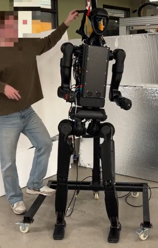
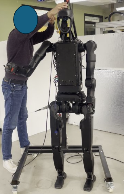
arm_waist_target — elbow extended 86° from zero, arm hanging straight down. Torso-to-wrist gain = 15.6.The difference between a 27-second successful balancing run, robust to 30N of external wrist forces, and violent leg thrashing within 0.16 seconds was this: the position of the left arm.
- Abstract
- Background: Pinocchio and Rigid-Body Dynamics
- Ill-Conditioned Jacobians: Amplification of Residuals
- Why RE1 and RE2 Never Hit This Regime
- Lower-Body Initial Configuration and Step-by-Step Analysis
- Step-by-Step Pinocchio Reconstruction: Steps 0–8
- Cascade Timeline and Causal Graph
- The Torso as a Kinematic Junction
- Discussion
- Recommendations
- Conclusions
- Appendix: Data Provenance
1. Abstract
During episode re3_real_encode_tr1, an RL balancing policy deployed on the H1-2 humanoid robot caused violent involuntary leg thrashing within 0.16 seconds of engagement, ultimately producing hip-pitch torques exceeding 428 N·m. The robot was stopped before structural damage occurred.
This document provides a ground-up technical analysis of the root cause. We cover: (1) a first-principles introduction to rigid-body dynamics and the Pinocchio framework; (2) the mathematics of estimating an external wrench from internal motor torques via the Jacobian pseudo-inverse; (3) why an ill-conditioned Jacobian amplifies any upstream torque residual into a spurious end-effector force; (4) a step-by-step numerical reconstruction of the cascade from policy steps 0–8; and (5) a revised causal hypothesis that inverts the previously posited narrative.
- In RE3, the left arm was in the
arm_waist_targetpose (shoulder pitched $-17°$ from motor zero, elbow extended $86°$ from motor zero), which physically corresponds to the arm hanging straight down and limp alongside the torso. In RE1/RE2 the arms were at motor zero, physically corresponding to forearms bent at the sides. The extended/limp left arm created a 15.6× torso→wrist-$F_z$ Jacobian amplification. - Both RE3 and RE2 began with similar large hip-roll position errors (~0.35–0.51 rad). The initial leg dynamics were comparable, but RE3's ill-conditioned Jacobian turned normal torso structural torques into catastrophic phantom wrist forces.
- The structural torque required by the torso motor to counteract leg dynamics was indistinguishable from normal, but with a 15.6× amplification it produced a $-533$ N spurious left wrist force.
- The policy interpreted this as a large external push at the wrist and commanded increasingly extreme leg targets, driving the torso torque higher, completing a positive feedback loop.
2. Background: Pinocchio and Rigid-Body Dynamics
2.1 What is Pinocchio?
Pinocchio is an open-source rigid-body dynamics library that operates on a robot model loaded from a URDF file. It represents the robot as a kinematic tree: a directed graph of rigid bodies (links) connected by joints. For the H1-2 we use a free-flyer root joint (6-DOF floating base) plus 27 actuated joints (legs, torso, arms), giving a configuration space of dimension $n_q = 34$ (7 free-flyer coefficients + 27 joint angles) and velocity space $n_v = 33$.
The library provides:
- Forward kinematics (
forwardKinematics): given $\bq$, compute the pose of every link/frame. - Recursive Newton-Euler Algorithm (
rnea): compute the joint torques $\btau$ required to achieve a given $(\bq, \dot\bq, \ddot\bq)$, including gravity. - Frame Jacobian (
computeFrameJacobian): the matrix $\bJ \in \mathbb{R}^{6 \times n_v}$ mapping joint velocities to the 6-D twist (linear+angular velocity) of a specific link frame.
The model is loaded from the H1-2 URDF with a free-flyer root (full model: nq=34, nv=33) for dynamics, and separately without the free-flyer (body model: nq=27, nv=27) for IK:
# robot_model.py — model initialization
self.model, _, self.visual_model = self._load_urdf_freeflyer(filename)
# full model: nq=34 (7 free-flyer + 27 motor), nv=33

self.model_body, self.collision_model_body, _ = self._load_urdf_body(filename)
# body-only model: nq=27 (motor only), nv=27

# _load_urdf_freeflyer: loads with pin.JointModelFreeFlyer() as root
model, collision_model, visual_model = pin.buildModelsFromUrdf(
    filename=urdf_path,
    package_dirs=os.path.dirname(urdf_path),
    root_joint=pin.JointModelFreeFlyer(),   # 6-DOF floating base
)
2.2 The Robot Configuration Vector
The 27 actuated joints are ordered as shown in Table 1. All data arrays (tau.npy, qpos.npy, target_dof.npy) use this ordering.
| Indices | Group | Joints |
|---|---|---|
| 0–5 | Left leg | l_hip_yaw, l_hip_pitch, l_hip_roll, l_knee, l_ank_pitch, l_ank_roll |
| 6–11 | Right leg | r_hip_yaw, r_hip_pitch, r_hip_roll, r_knee, r_ank_pitch, r_ank_roll |
| 12 | Torso | torso |
| 13–19 | Left arm | L_sh_pitch, L_sh_roll, L_sh_yaw, L_elbow, L_wr_roll, L_wr_pitch, L_wr_yaw |
| 20–26 | Right arm | R_sh_pitch, R_sh_roll, R_sh_yaw, R_elbow, R_wr_roll, R_wr_pitch, R_wr_yaw |
2.3 Forward Kinematics and the Frame Jacobian
Given a configuration $\bq$, forward kinematics computes the homogeneous transform $T^{w}_{f}(\bq) \in SE(3)$ from the world frame to any target frame $f$. For the left wrist yaw link:
$$T^{w}_{\text{lwrist}}(\bq) = T^{w}_{\text{pelvis}} \cdot T^{\text{pelvis}}_{\text{torso}} \cdot T^{\text{torso}}_{\text{L\_sh\_pitch}} \cdots T^{\text{L\_elbow}}_{\text{lwrist}}$$where each factor depends only on the joint angles along the kinematic chain.
The geometric Jacobian of frame $f$ in the LOCAL_WORLD_ALIGNED convention is the $6 \times n_v$ matrix:
$$\bJ_f(\bq) \triangleq \frac{\partial}{\partial \bq} \begin{pmatrix} v_f \\ \omega_f \end{pmatrix}$$such that the 6-D twist of frame $f$ is $\xi_f = \bJ_f \dot\bq$. For our 27-DOF motor space the Jacobian has shape $6 \times 27$.
# robot_model.py — get_frame_jacobian
def get_frame_jacobian(self, frame_name: str, q: np.ndarray=None, imu_quat=None):
    '''
    Get the frame jacobian in the world frame
    q is motor-only (27), returns motor-only jacobian (6 x 27)
    '''
    if q is not None:
        q_full = self.full_q(q, imu_quat)   # expand 27 → 34 with free-flyer
        data = self.model.createData()
    else:
        q_full = self.full_q(self.state['q'])
        data = self.data

    pin.forwardKinematics(self.model, data, q_full)
    pin.updateFramePlacements(self.model, data)

    frame_id = self.model.getFrameId(frame_name)
    jacobian_full = pin.computeFrameJacobian(
        self.model, data, q_full, frame_id,
        pin.ReferenceFrame.LOCAL_WORLD_ALIGNED   # world-aligned axes at frame origin
    )
    # strip the 6 free-flyer columns → return 6 x 27 motor-only Jacobian
    return jacobian_full[:, FREEFLYER_NV:]
2.4 Recursive Newton-Euler Algorithm (RNEA): Gravity Compensation
The RNEA computes, for any $(\bq, \dot\bq, \ddot\bq)$, the joint torques $\btau = \text{RNEA}(\bq, \dot\bq, \ddot\bq)$ satisfying the equations of motion:
$$M(\bq)\ddot\bq + C(\bq,\dot\bq)\dot\bq + \bm{g}(\bq) = \btau + \bJ^T\bF_\text{ext}$$where $M$ is the mass matrix, $C$ the Coriolis/centrifugal matrix, $\bm{g}$ the gravity torque vector, and $\bF_\text{ext}$ any external wrench.
Setting $\dot\bq = \ddot\bq = 0$ isolates gravity:
$$\btau_\text{grav}(\bq) = \text{RNEA}(\bq, \bm{0}, \bm{0}) \tag{1}$$This is the gravity compensation torque: the exact joint torques a perfectly rigid robot must exert merely to hold itself stationary against gravity at configuration $\bq$.
# robot_model.py — get_gravity_compensation
def get_gravity_compensation(self, q: np.ndarray=None, imu_quat=None):
    q = self.state['q'] if q is None else q
    q_full = self.full_q(q, imu_quat)   # 27 motor → 34 with free-flyer + IMU orientation
    tau_full = pin.rnea(
        self.model,
        self.data,
        q_full,
        np.zeros(self.model.nv),   # dq = 0: no velocity
        np.zeros(self.model.nv)    # ddq = 0: no acceleration
    )
    # tau_full has shape (33,): 6 free-flyer + 27 motor
    return tau_full[FREEFLYER_NV:]   # return motor-only slice (27,)
2.5 Wrench Estimation via Pseudo-Inverse
robot_model.py::get_frame_wrench estimates an external wrench at frame $f$ as follows:
# robot_model.py — get_frame_wrench (the function at the center of this incident)
def get_frame_wrench(self, frame_name: str,
                     q: np.ndarray=None, tau: np.ndarray=None, imu_quat=None):
    q   = self.state['q']   if q   is None else q
    tau = self.state['tau'] if tau is None else tau
    tau_gravity = self.get_gravity_compensation(q, imu_quat)   # eq (1)
    jac         = self.get_frame_jacobian(frame_name, q, imu_quat)   # J: 6×27
    wrench      = np.linalg.pinv(jac.T) @ (tau - tau_gravity)        # eq (2)
    return wrench   # [Fx, Fy, Fz, Mx, My, Mz] in N, N·m
Listing 1. The wrench estimator as it existed at the time of RE3. The tau_gravity is subtracted to isolate the residual, then the pseudo-inverse of $J^T$ maps that residual to an estimated end-effector wrench.
The mathematical basis is the static equilibrium assumption: if the only source of unexplained joint torque is an external wrench $\bw \in \mathbb{R}^{6}$ applied at frame $f$, then
$$\btau_\text{meas} - \btau_\text{grav} = \bJ_f^T \bw \tag{2}$$Solving for $\bw$ with the Moore-Penrose pseudo-inverse:
$$\hat\bw = \pinv{(\bJ_f^T)} \left(\btau_\text{meas} - \btau_\text{grav}\right) = \pinv{(\bJ_f^T)} \, \btau_\text{res} \tag{3}$$Here $\pinv{(\bJ_f^T)} \in \mathbb{R}^{6 \times 27}$ is the $6 \times 27$ pseudo-inverse of $\bJ_f^T \in \mathbb{R}^{27 \times 6}$. When $\bJ_f$ is full column rank (rank 6), $\pinv{(\bJ_f^T)} = (\bJ_f \bJ_f^T)^{-1} \bJ_f$.
This function is called continuously during the gravity compensation controller and its output is fed directly to the RL policy as part of the observation vector:
# gravity_comp_controller.py — how get_frame_wrench is called in practice
def gravity_compensation_step(self):
    left_wrench  = self.robot_model.get_frame_wrench(self.left_ee_name)
    right_wrench = self.robot_model.get_frame_wrench(self.right_ee_name)
    left_force   = np.linalg.norm(left_wrench[:3])   # Fz is left_wrench[2]
    right_force  = np.linalg.norm(right_wrench[:3])
    # wrench is used to gate integral control and — critically —
    # as direct input to the RL policy encoder
Critical assumption and its violation
Equation (2) assumes that $\btau_\text{res}$ arises exclusively from $\bw$. In practice, any other unexplained torque—inertial loading, joint friction, dynamic oscillations in upstream joints—is spuriously attributed to the external wrench at frame $f$. Concretely, if joint $j$ has a residual $r_j = \tau_j - \tau^\text{grav}_j$, its contribution to the estimated wrist force is:
$$\Delta\hat\bw_j = \pinv{(\bJ_f^T)}_{[:,j]} \cdot r_j \tag{4}$$The scalar $g_j \triangleq \left[\pinv{(\bJ_f^T)}\right]_{[3,j]}$ is the torso-to-wrist-$F_z$ gain for joint $j$. A large $|g_j|$ means a small torque at joint $j$ appears as a large force at the wrist. This gain is determined entirely by the arm geometry—and it is what makes the arm pose a safety-critical parameter.
3. Ill-Conditioned Jacobians: Amplification of Residuals
3.1 Singular Values and the Pseudo-Inverse
The singular value decomposition (SVD) of $\bJ \in \mathbb{R}^{6 \times 27}$ is:
$$\bJ = U \Sigma V^T, \quad \Sigma = \operatorname{diag}(\sigma_1, \ldots, \sigma_6), \quad \sigma_1 \geq \cdots \geq \sigma_6 \geq 0$$The pseudo-inverse is:
$$\pinv{\bJ} = V \Sigma^{-1} U^T, \quad \Sigma^{-1} = \operatorname{diag}(1/\sigma_1, \ldots, 1/\sigma_6)$$The condition number $\kappa = \sigma_1/\sigma_6$ measures how much the pseudo-inverse amplifies errors. A component of $\btau_\text{res}$ aligned with the singular direction corresponding to $\sigma_6$ is amplified by a factor $1/\sigma_6$.
3.2 2D RRR Arm: A Worked Example
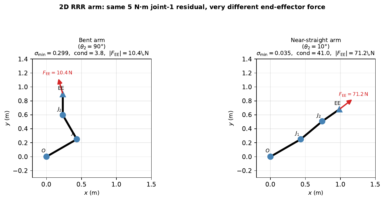
Consider a planar 3-link arm with revolute joints $\theta_1, \theta_2, \theta_3$. The end-effector position is:
$$x_{ee} = \ell_1 c_1 + \ell_2 c_{12} + \ell_3 c_{123}, \quad y_{ee} = \ell_1 s_1 + \ell_2 s_{12} + \ell_3 s_{123}$$where $c_k \equiv \cos\!\sum_{i \le k}\theta_i$, etc. The $2 \times 3$ Jacobian maps $\dot\btheta$ to end-effector velocity, and its transpose maps end-effector forces to joint torques: $\btau = \bJ^T \bF_{ee}$. Inverting: $\hat\bF_{ee} = \pinv{(\bJ^T)} \btau_\text{res}$.
As $\theta_2 \to 0$ (arm near-straight), the second and third link become collinear, and two rows of $\bJ$ become nearly dependent. The smallest singular value $\sigma_{\min} \to 0$, making $\pinv{(\bJ^T)}$ unbounded. Figure 1 shows the numerical outcome: with $\theta_2 = 90°$ (bent) a 5 N·m joint residual produces a 10 N end-effector force; with $\theta_2 = 10°$ the same residual produces 71 N — a 7× amplification from geometry alone.
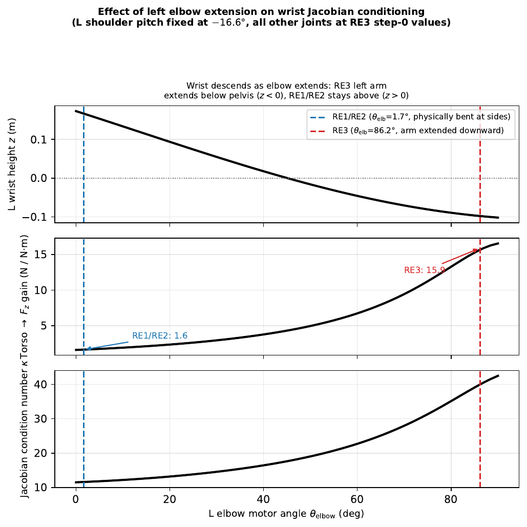
3.3 The Torso-to-Wrist Amplification in the H1-2
In the H1-2 kinematic tree, the torso joint sits directly between the pelvis and both arms. Its Jacobian column for the wrist frame encodes the cross-product lever arm from torso rotation to wrist linear velocity:
$$\bJ_\text{lwrist, torso}^\text{linear} = \bm{\omega}_\text{torso} \times \bm{r}_{\text{torso}\to\text{wrist}}$$where $\bm{\omega}_\text{torso}$ is the unit rotation axis of the torso joint and $\bm{r}$ is the vector from torso joint to wrist frame. The magnitude of this lever arm determines how strongly a torso torque residual projects onto the wrist $F_z$ direction.
Physical configuration at RE3 episode start:
- RE1/RE2
- Arms at motor zero $\approx 0°$: physically the bent-at-sides configuration. Elbow at $0°$ means the forearm is roughly horizontal, wrist at approximately shoulder height. Measured: left wrist at $(0.23,\ 0.21,\ +0.09)$ m — above the pelvis plane. Torso-to-wrist gain = 1.5.
- RE3
- Left arm in
arm_waist_target: shoulder pitch $= -17°$, left elbow $= 86°$ from motor zero. The forearm has rotated $86°$ from horizontal, pointing nearly straight down. Forward kinematics: left wrist at $(0.17,\ 0.20,\ -0.10)$ m — below the pelvis plane, 0.52 m below the shoulder. Torso-to-wrist gain = 15.6.
The torso-to-wrist-$F_z$ gain, $g_\text{torso}$, measured at each policy step from actual episode data:
| Step | RE3 (disaster) | RE2 (good) | ||
|---|---|---|---|---|
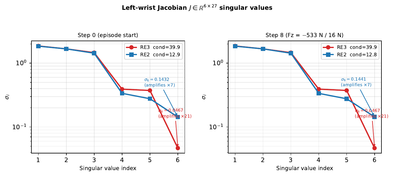
| $g_\text{torso}$ (N/N·m) | $\kappa$ | $g_\text{torso}$ | $\kappa$ | |
| 0 | 15.62 | 39.9 | 1.51 | 12.9 |
| 1 | 15.62 | 39.9 | 1.51 | 12.9 |
| 2 | 15.62 | 39.9 | 1.51 | 12.9 |
| 3 | 15.45 | 39.5 | 1.51 | 12.9 |
| 4 | 15.30 | 39.1 | 1.52 | 12.9 |
| 5 | 15.12 | 38.7 | 1.52 | 12.8 |
| 6 | 15.04 | 38.5 | 1.53 | 12.8 |
| 7 | 15.06 | 38.6 | 1.53 | 12.8 |
| 8 | 15.62 | 39.9 | 1.53 | 12.8 |
The RE3 gain ($\approx$15.6 N/N·m) is 10× larger than RE2's ($\approx$1.5 N/N·m) throughout all 9 steps. This single number fully explains the difference in outcomes.
4. Why RE1 and RE2 Never Hit This Regime
4.1 Motor Zero = Physically Bent at Sides
A key subtlety is what the arm motor zeros correspond to physically. On the H1-2, the arm motor zero position is not the natural straight-down hang; it is the forearms bent horizontally at the sides configuration — both arms at roughly 90° at the elbows, forearms pointing outward/forward at approximately waist height.
This means:
- RE1/RE2 arm motor readings $\approx 0°$: arms physically in the bent-at-sides pose. Wrist is at approximately $z = +0.09$ m (above the pelvis plane). Arm is folded, wrist is close to the torso. Torso→$F_z$ gain = 1.5.
- RE3 left arm (
arm_waist_target): elbow motor at $+86°$ from zero. Physically the forearm has swung $86°$ down from the horizontal reference, so the arm is nearly fully extended straight down. Wrist drops to $z = -0.10$ m (below the pelvis), 0.52 m below the shoulder. Torso→$F_z$ gain = 15.6.
The bent-at-sides (motor zero) configuration is a well-conditioned starting point. The wrist is close to the torso, the lever arm is short, and the Jacobian gain is low. The limp/extended configuration is the singular one.
4.2 Arm Range of Motion in RE1/RE2
| Joint | RE1 (2620 steps) | RE2 (1357 steps) | RE3 (77 steps) | |||
|---|---|---|---|---|---|---|
| min (°) | max (°) | min (°) | max (°) | min (°) | max (°) | |
| L_sh_pitch | −0.7 | +3.2 | −0.5 | +1.6 | −27.2 | −4.6 |
| L_sh_roll | −0.3 | +0.9 | −0.3 | +0.4 | −5.2 | +9.8 |
| L_elbow | +1.5 | +4.0 | +1.4 | +2.0 | +82.9 | +89.4 |
| R_sh_pitch | −0.2 | +3.9 | −0.1 | +2.7 | −65.5 | −29.4 |
| R_sh_roll | −0.3 | +0.8 | −0.2 | +0.4 | −38.5 | −18.1 |
| R_elbow | +1.3 | +5.2 | +1.3 | +3.4 | +26.0 | +39.9 |
The data is definitive: in RE1 and RE2, all arm joints remained within $\pm 5°$ of their motor zeros throughout the entire runs. The arms never deviated from the bent-at-sides configuration. RE3 is the only run where an arm was placed in the extended/limp configuration.
The arms never moved during these runs because the RL policy has no arm action outputs: arm positions are held at whatever initial configuration is set by the deploy script. In RE1/RE2 that configuration was motor zero (bent at sides); in RE3 it was arm_waist_target (left arm extended downward).
5. Lower-Body Initial Configuration and Step-by-Step Analysis
5.1 Initial Configuration Errors at Episode Start
Both RE2 and RE3 began with substantial lower-body position errors relative to the policy's first commanded targets. Critically, the errors are comparable in magnitude: both episodes start with hip-roll errors of 0.35–0.51 rad ($\approx$20–30°).
| Joint | RE3 $q$ | RE3 tgt | RE3 err | RE2 err |
|---|---|---|---|---|
| l_hip_yaw | −0.011 | −0.059 | +0.048 | +0.085 |
| l_hip_pitch | −0.139 | −0.250 | +0.111 | +0.049 |
| l_hip_roll | +0.006 | +0.361 | −0.355 | −0.514 |
| l_knee | +0.385 | +0.675 | −0.289 | −0.247 |
| l_ank_pitch | −0.367 | −0.143 | −0.224 | −0.142 |
| r_hip_yaw | −0.004 | −0.053 | +0.049 | +0.075 |
| r_hip_pitch | −0.162 | −0.090 | −0.073 | −0.005 |
| r_hip_roll | +0.007 | −0.344 | +0.351 | +0.445 |
| r_knee | +0.392 | +0.667 | −0.276 | −0.267 |
| r_ank_pitch | −0.345 | −0.135 | −0.210 | −0.122 |
| torso | −0.001 | +0.000 | −0.001 | −0.005 |
Both episodes are in essentially identical initial lower-body configurations. The subsequent divergence is not due to different initial conditions in the legs—it is due to the arms.
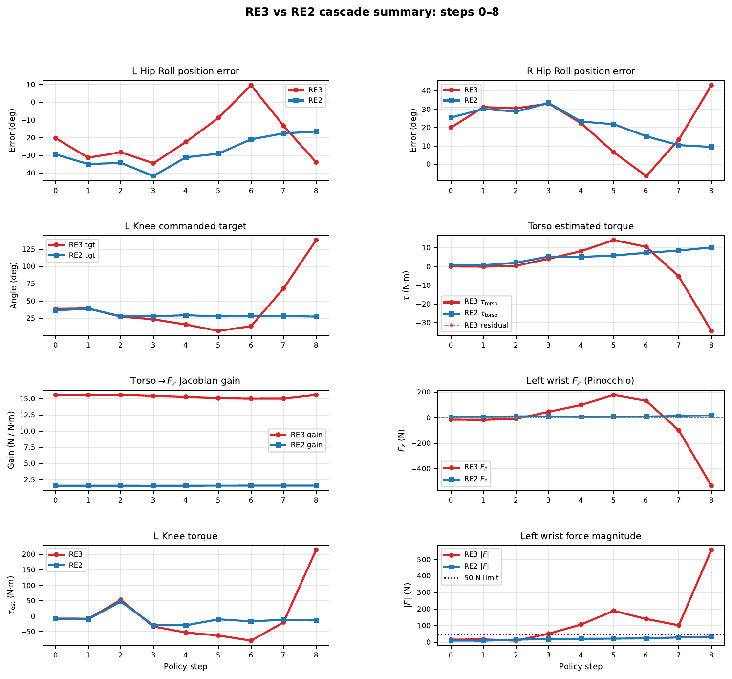
5.2 Step-by-Step Position Errors
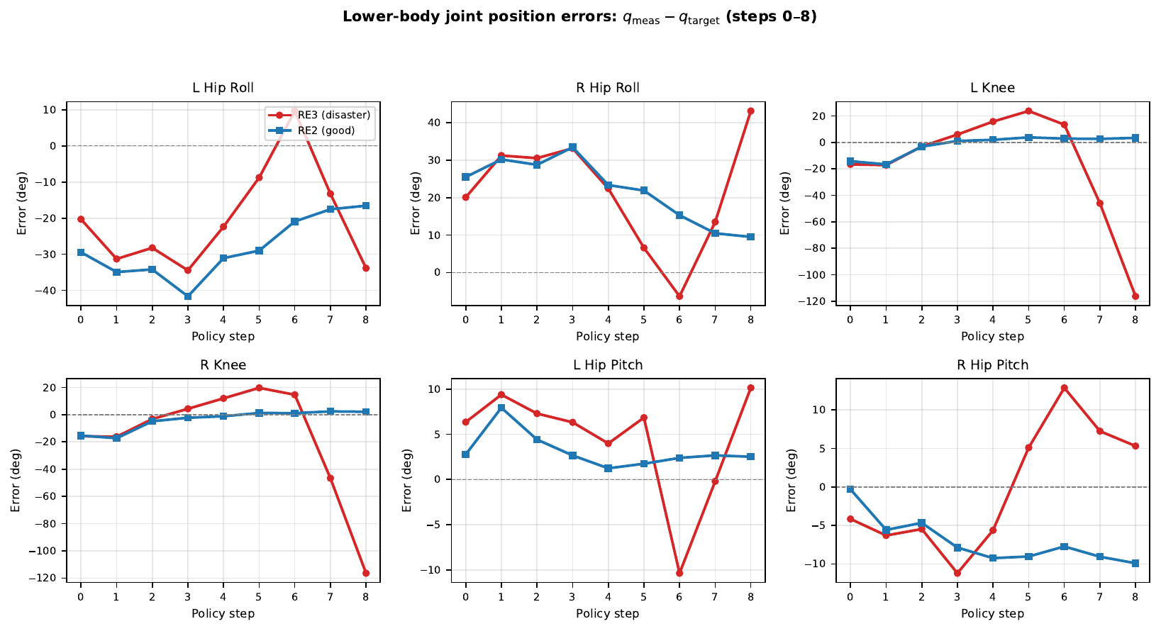
Notable observations:
- The hip-roll errors in both RE2 and RE3 start at the same magnitude (20–34°) and evolve similarly through the first 2–3 steps.
- RE3's errors grow substantially by steps 6–8 (hip yaw error exceeds 40°, knee error reaches $-117°$ by step 8).
- In RE2 the errors remain bounded: hip roll oscillates but stays within $\pm35°$, knee within $\pm10°$, throughout all 8 steps.
The growing errors in RE3 are not the root cause of the disaster; they are a consequence of the policy receiving bad wrench feedback and issuing increasingly extreme leg commands.
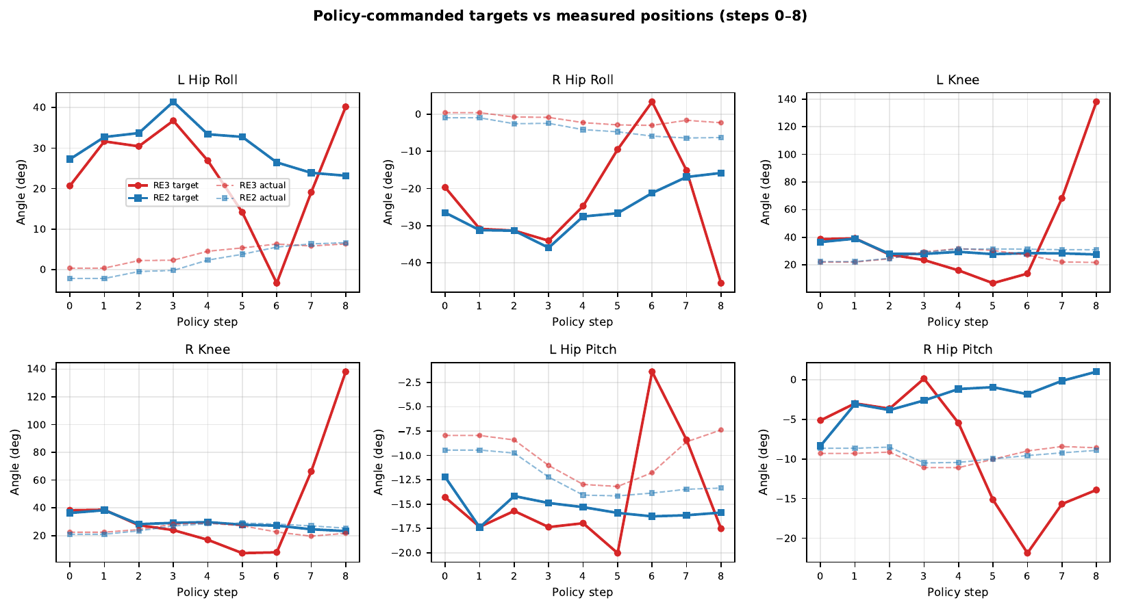
5.3 Commanded Targets
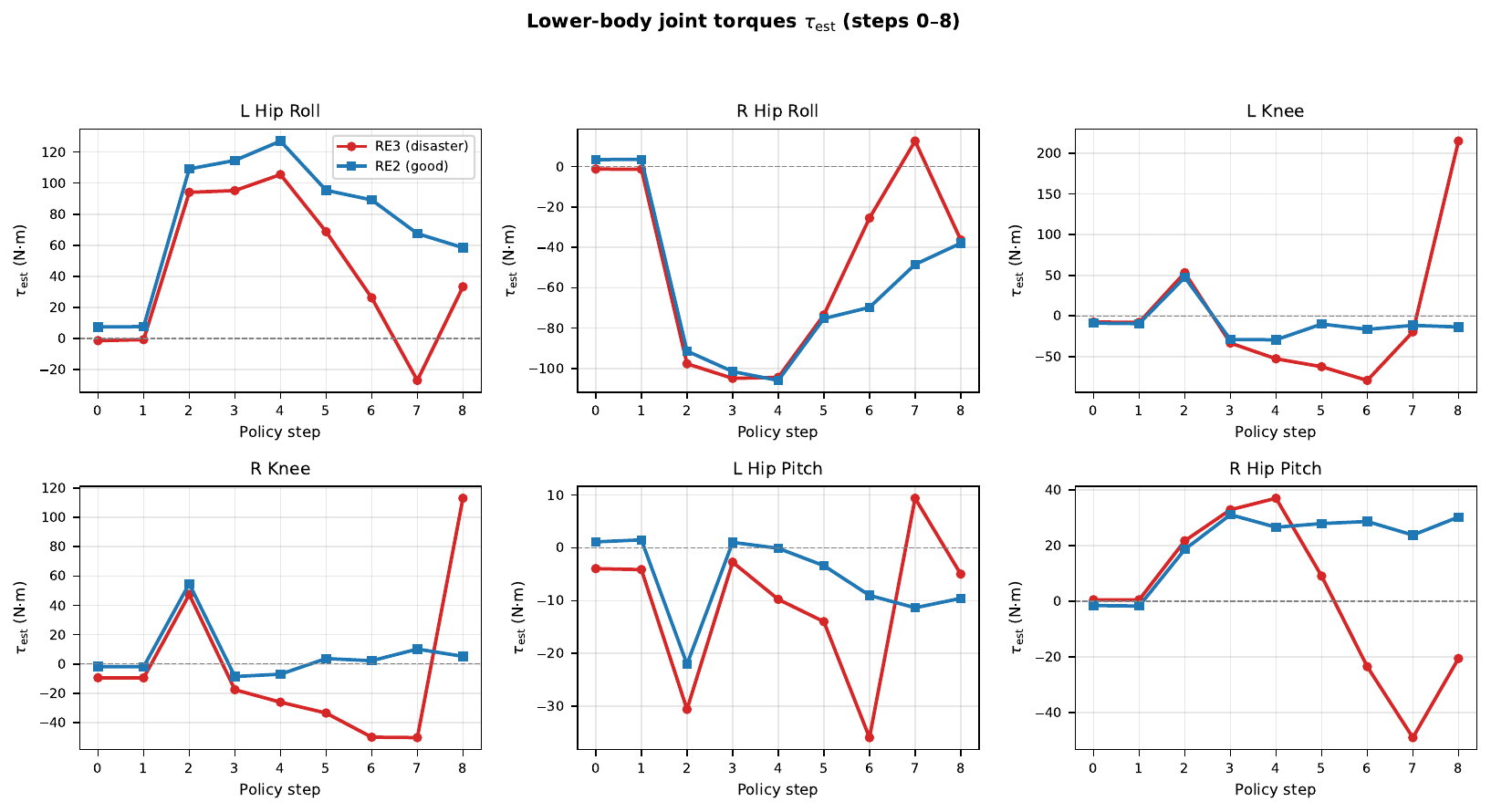
5.4 Measured Torques
6. Step-by-Step Pinocchio Reconstruction: Steps 0–8
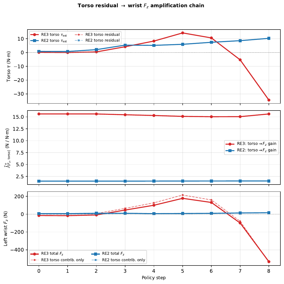
6.1 Complete Numerical Trace
The table below shows the full Pinocchio reconstruction at each step, side by side for RE2 and RE3. The torso residual $r_\text{torso} = \tau^\text{est}_\text{torso} - \tau^\text{grav}_\text{torso}$ is the single dominant source of the wrist force in RE3.
| RE3 (disaster) | RE2 (good) | |||||||
|---|---|---|---|---|---|---|---|---|
| Step | $r_\text{torso}$ | $g_\text{torso}$ | $F_z$ | $|F|$ | $r_\text{torso}$ | $g_\text{torso}$ | $F_z$ | $|F|$ |
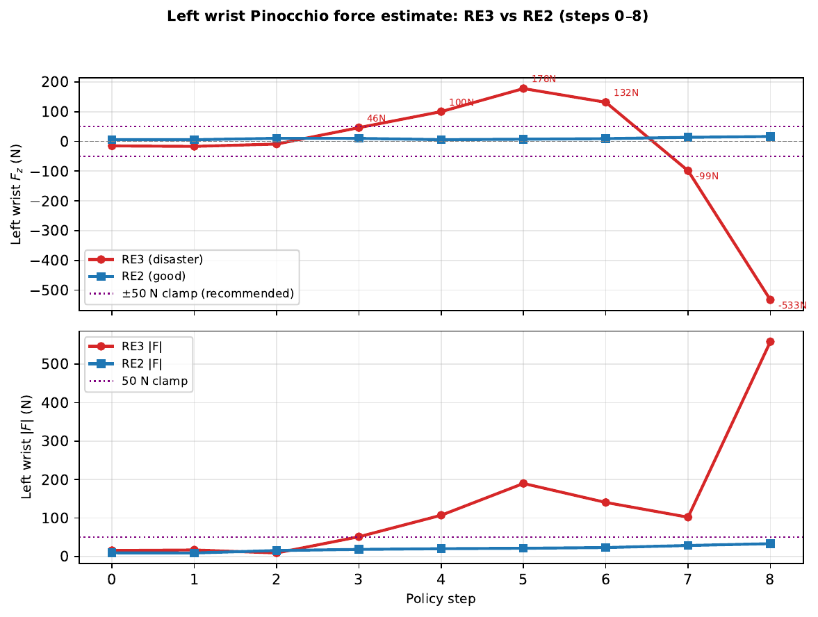
| 0 | 0.12 | 15.62 | −15.2 | 15.3 | 0.82 | 1.51 | 6.2 | 9.4 |
| 1 | 0.00 | 15.62 | −16.7 | 16.9 | 0.76 | 1.51 | 5.8 | 9.0 |
| 2 | 0.47 | 15.62 | −8.9 | 9.0 | 2.11 | 1.51 | 10.4 | 15.4 |
| 3 | 4.22 | 15.45 | +46.3 | 51.2 | 5.39 | 1.51 | 10.1 | 18.3 |
| 4 | 8.32 | 15.30 | +100.2 | 107.1 | 5.22 | 1.52 | 5.9 | 20.1 |
| 5 | 14.24 | 15.12 | +177.8 | 189.7 | 5.98 | 1.52 | 7.4 | 21.3 |
| 6 | 10.61 | 15.04 | +131.5 | 140.4 | 7.44 | 1.53 | 9.3 | 23.1 |
| 7 | −5.27 | 15.06 | −98.6 | 102.0 | 8.61 | 1.53 | 13.7 | 28.5 |
| 8 | −34.45 | 15.62 | −532.9 | 558.2 | 10.31 | 1.53 | 16.5 | 33.2 |
Key observations:
- At step 0, even before any leg motion, RE3 already shows $F_z = -15.2$ N versus RE2's 6.2 N, solely due to the 10× higher Jacobian gain.
- By step 5, RE3 has $F_z = +178$ N—already far above any real wrist load—while RE2 stays at 7.4 N. At this point the policy has already been fed damaging feedback for 5 steps.
- The RE3 torso residual $r_\text{torso}$ grows from 0.12 to $-34.45$ N·m over 9 steps, driven by the extreme leg commands the policy is now issuing in response to the bad wrench estimates.
- RE2's torso residual reaches 10.3 N·m by step 8 (similar in trend), but the 1.5× gain keeps the wrist force at 16.5 N.
6.2 Per-Joint Decomposition at Step 8
Applying equation (4) to every joint at step 8 reveals that virtually the entire $-533$ N wrist force originates from a single joint:
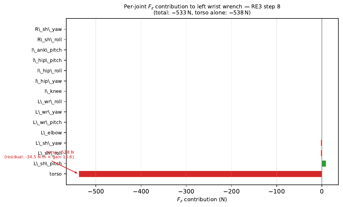
| Joint | $\tau_\text{meas}$ (N·m) | $\tau_\text{grav}$ (N·m) | $r$ (N·m) | $\Delta F_z$ (N) |
|---|---|---|---|---|
| torso | −34.45 | ≈0 | −34.45 | −538 |
| L_sh_pitch | −5.10 | −3.79 | −1.31 | +9.4 |
| L_sh_roll | +0.79 | +0.15 | +0.64 | −2.6 |
| L_sh_yaw | +0.34 | −0.01 | +0.34 | −2.3 |
| All others (24 joints) | — | — | large | <±1 each |
| Total | −532.9 |
The leg joints (l_knee residual $= +213$ N·m; r_knee $= +111$ N·m) do not contribute to wrist $F_z$ because the leg columns of the wrist Jacobian are near zero—the legs are kinematically disconnected from wrist translation. The torso joint is the kinematic bridge between the legs and arms; its unique position in the tree gives it a large wrist Jacobian column.
6.3 Jacobian Singular Value Spectrum
7. Cascade Timeline and Causal Graph
7.1 Revised Causal Hypothesis
The original framing described an "imaginary" wrist force causing the leg reaction. The data supports a more nuanced reading: the wrist force was indeed spurious, but the underlying structural dynamics that caused it were real. The cascade follows a feedback loop:
Causal Graph — RE3 Disaster
Arms inarm_waist_target |
+ | Hip-roll error ~0.5 rad at $t=0$ |
| ↓ | ↓ | |
| Torso→wrist $F_z$ gain = 15.6 (10× larger than RE2) |
PD commands large leg torques (~100 N·m hip-roll) |
|
| ↓ | ||
| Structural dynamics excite torso joint |
||
| ↓ | ||
| ↘ | Torso residual $r_\text{torso}$ grows 0.12 → −34.5 N·m over steps 0–8 |
|
| ↓ (gain × residual) | ||
| Spurious wrist $F_z = -532$ N | ||
| ↓ | ||
| Policy commands extreme leg targets (knee target → 2.41 rad = 138°) |
||
| ↓ | ||
| Knee torques → 329 N·m | ||
| ↓ | ||
| Torso fights reaction: −34 N·m → feedback ↑ | ||
7.2 Complete Event Timeline
| Step | Time (s) | $F_z$ (N) | Torso $\tau$ (N·m) | Event |
|---|---|---|---|---|
| 0 | 22.465 | −15.2 | 0.12 | Policy start; arm Jacobian gain = 15.6 |
| 1 | 22.472 | −16.7 | 0.00 | First PD torques; legs near-static |
| 2 | 22.490 | −8.9 | 0.47 | Hip-roll PD fires; l_hip_roll 94 N·m |
| 3 | 22.509 | +46.3 | 4.22 | Torso residual builds; $F_z$ exceeds 50 N |
| 4 | 22.529 | +100.2 | 8.32 | Policy already sensing 100 N push |
| 5 | 22.549 | +177.8 | 14.24 | Knee targets start growing; policy alarmed |
| 6 | 22.570 | +131.5 | 10.61 | Hip yaw targets spike to ±0.43 rad |
| 7 | 22.590 | −98.6 | −5.27 | Knee target reaches 1.19 rad (68°) |
| 8 | 22.609 | −532.9 | −34.45 | Torso fights inertial kick; $F_z$ = −533 N |
| 9–15 | 22.63–22.75 | → −715 | escal. | Knee target = 2.41 rad; escalation |
| 43–46 | 23.31–23.38 | −2596 | — | Peak wrist force |
| 64 | 23.737 | — | — | l_hip_pitch = 428 N·m peak |
| 76 | 23.978 | — | — | Episode terminated |
7.3 Cascade Summary
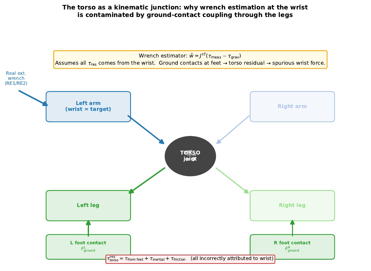
8. The Torso as a Kinematic Junction: Unavoidable Contamination
8.1 Why Torso Torque Is Never Zero During a Real Run
Equation (2) assumes the sole source of torque residual is an external wrench at the wrist. In any real deployment this assumption is structurally violated because the torso joint sits at a kinematic junction: the legs (with ground-contact forces below) and the arms (to be estimated above) both connect to it.
Even in a nominally stationary standing pose, the robot is never in perfect bilateral stance. The leg joints are slightly bent, the CoM may be marginally offset, and the ground-contact forces at the left and right feet are unequal. These real external wrenches at the feet propagate up the leg kinematic chain and appear as residual torques at every joint from the ankles to the torso:
$$\tau_\text{torso}^\text{res} = \underbrace{\tau_{\text{feet}\to\text{torso}}}_{\text{ground-contact coupling}} + \underbrace{\tau_\text{inertial}}_{\text{dynamic loading}} + \underbrace{\tau_\text{friction}}_{\text{joint friction}}$$None of these contributions has anything to do with an external force at the wrist. The wrench estimator, however, cannot distinguish them: it projects everything in $\btau_\text{res}$ onto the wrist frame via $\pinv{(\bJ^T)}$.
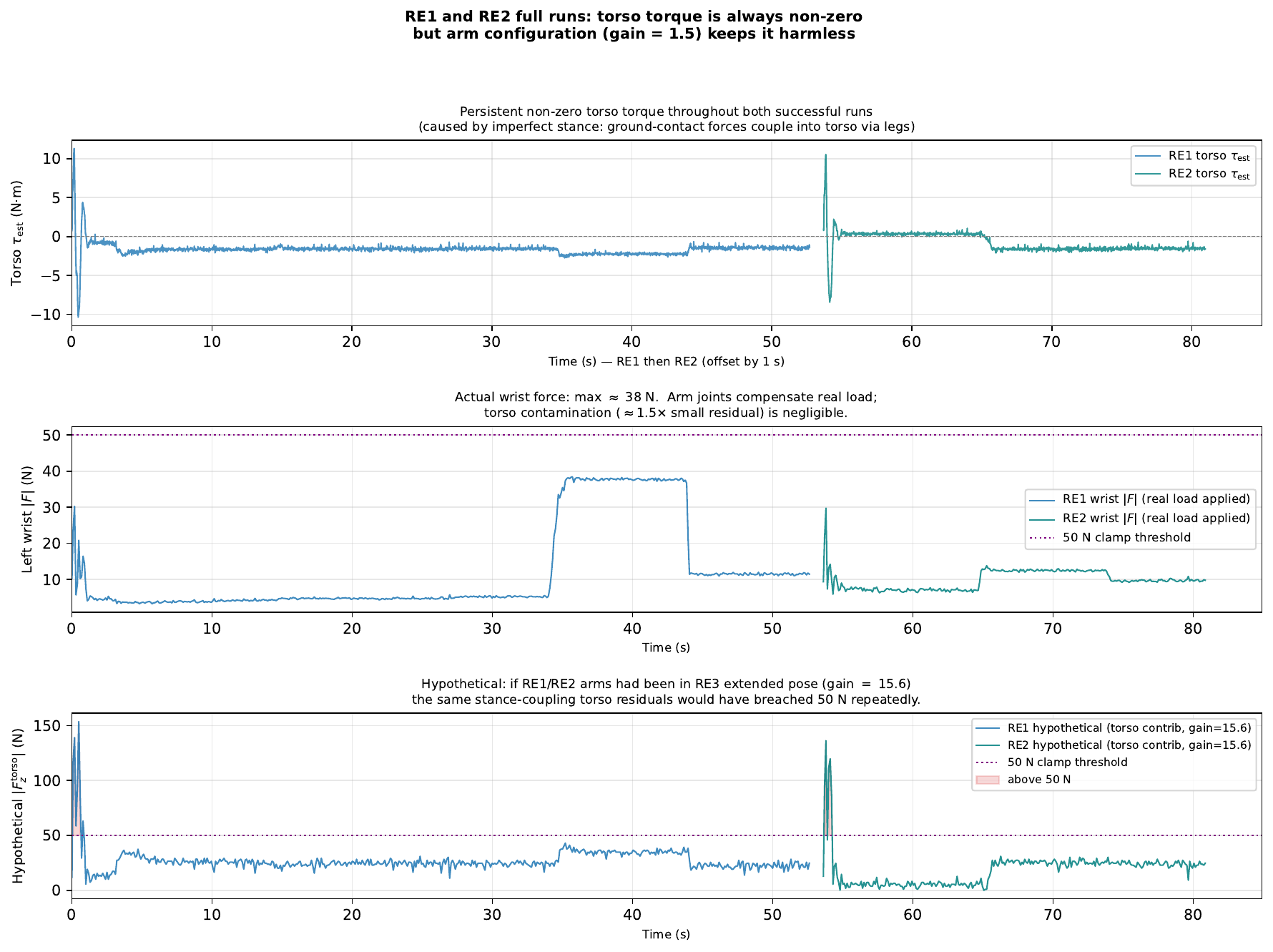
8.2 RE1/RE2: Torso Residual Always Present, Never Catastrophic
| Episode | Mean $|\tau_\text{torso}|$ (N·m) | Std | Max $|\tau_\text{torso}|$ | p99 |
|---|---|---|---|---|
| RE1 (2620 steps) | 1.6 | 0.9 | 11.3 | 4.0 |
| RE2 (1357 steps) | 0.8 | 1.4 | 10.5 | 6.6 |
At the RE1/RE2 Jacobian gain of $\approx$1.5, these torso residuals produce wrist-force contamination of only ~1–2 N on average and ~14 N at the worst. This is swamped by the actual external loads the experimenter is applying to the arms during those runs.
8.3 The Fundamental Indistinguishability
The torso's $\tau_\text{res}$ is a superposition of all external loads attached to its kinematic tree:
$$\btau_\text{res} = \bJ_{\text{L-wrist}}^T \bw_{\text{L-wrist}} + \bJ_{\text{R-wrist}}^T \bw_{\text{R-wrist}} + \bJ_{\text{L-foot}}^T \bw_{\text{L-foot}} + \bJ_{\text{R-foot}}^T \bw_{\text{R-foot}} + \btau_\text{inertial}$$Projecting through $\pinv{(\bJ_\text{wrist}^T)}$ recovers $\bw_\text{wrist}$ exactly only if the foot and inertial terms are zero. When a real wrist load is present and large, it dominates the torso residual and the estimate is approximately correct (RE1/RE2). When there is no real wrist load, the foot-coupling and inertial terms are the only contributors, and the estimator attributes all of them to an imaginary wrist force. The torso's Jacobian gain then determines whether this error is negligible (gain = 1.5) or catastrophic (gain = 15.6).
9. Discussion
9.1 Original vs. Revised Hypothesis
The original investigation framed the disaster as a spurious Pinocchio force causing a leg reaction. This was correct in direction but incomplete in mechanism. A cleaner framing:
The robot's own structural dynamics (normal leg PD corrections) drove a real torso torque of $-34$ N·m by step 8. Under a well-conditioned Jacobian (RE2, gain 1.5), this is invisible (→ 15 N wrist force). Under the ill-conditioned Jacobian set by the arm_waist_target pose (RE3, gain 15.6), the same torso torque becomes a $-532$ N phantom wrist force, which the RL policy then desperately and destructively tries to counteract.
The wrench is spurious, but it originates from a real mechanical event (the torso joint fighting structural reaction forces), not from a numerical bug or modelling error. The amplification is geometric, determined entirely by the arm pose at wrench estimation time.
9.2 Why the Arms Were in the Bad Pose
The arm_waist_target pose is defined in the deploy configuration:
arm_waist_target = [0.0,              # torso
                    -0.3, 0.0, 0.0, 1.5, 0.0, 0.0, 0.0,   # left arm
                    -0.9, -0.47, 0.0, 0.5, 0.0, 0.0, 0.0]  # right arm
#                    ^sh_pitch        ^elbow (1.5 rad = 86° from motor zero)
This places the left shoulder pitch at $-0.3$ rad ($-17°$ from motor zero) and the left elbow at $1.5$ rad ($+86°$ from motor zero, which physically rotates the forearm $86°$ from the bent-at-sides reference, extending the arm nearly straight down). The intent of arm_waist_target is presumably to position the hands near the robot's waist for future manipulation tasks. However, this configuration was never tested for compatibility with the wrench-conditioned RL policy.
9.3 Why RE1 and RE2 Were Safe
RE1 and RE2 ran with arms remaining at motor zero ($< 5°$ variation throughout entire thousands-of-step runs). Motor zero on the H1-2 physically corresponds to forearms bent at the sides — a compact, well-conditioned arm pose with Jacobian gain $\approx 1.5$.
Had RE1 or RE2 been run with the arms in the RE3 extended pose, the same torso residuals they already exhibited would have produced catastrophically large spurious wrist forces:
$$|F_z|_\text{hypothetical} = 15.6 \times 9\,\text{N·m} = 140\,\text{N} \quad \text{(from torso alone)}$$This is well above the 50 N threshold that triggered catastrophic leg commands in RE3.
9.4 Implications
- Arm pose is a safety-critical parameter for the wrench estimator. Any deployment that uses a non-default arm configuration must verify the resulting torso-to-wrist Jacobian gain is acceptable ($< 3$ N/N·m recommended).
- The wrench estimator's assumption is fundamentally violated in full-body motion. The assumption $\btau_\text{res} = \bJ^T\bw$ is a static approximation. During dynamic whole-body motion, inertial and Coriolis torques are the dominant residuals, and they have nothing to do with external forces at the wrist.
- A hard output clamp would have prevented this disaster. Had the wrench output been clamped to $|\bm{F}| < 50$ N before passing to the encoder, step 3's 46 N would have been truncated and the policy never received damaging feedback.
10. Recommendations
| Priority | Type | One-line summary |
|---|---|---|
| Critical | Output clamp | ±50 N hard clip before passing to encoder |
| Critical | Pre-flight | Check Jacobian gain < 3 and initial hip error < 0.15 rad |
| High | Better estimator | Stacked 4-endpoint estimator; explicitly models foot contacts |
| High | Sanity check | Arm-vs-torso residual ratio flags structural contamination |
| High | Gravity comp. | Pass IMU quaternion to get_frame_wrench |
| Medium | Monitor | Log Jacobian condition number; disable if $\kappa > 20$ |
| Medium | Watchdog | Disengage policy if $|\bm{F}| > 100$ N for $> 3$ steps |
R1. Output Clamp (Immediate, One Line of Code)
Add a hard magnitude clamp to get_frame_wrench before returning:
wrench = np.linalg.pinv(jac.T) @ (tau - tau_gravity)
wrench[:3] = np.clip(wrench[:3], -F_max, F_max)   # add this line
return wrench
with $F_\text{max} = 50$ N as a conservative starting point. This would have completely prevented the RE3 disaster: the first out-of-bound estimate ($F_z = +46$ N) would have been clipped at step 3, and the policy would never have received damaging feedback. 50 N is intentionally conservative—the RL policy was trained with wrist forces in the range the experimenter could apply by hand; anything larger almost certainly reflects estimator breakdown.
R2. Pre-flight Safety Checks
Check A: Jacobian condition / torso gain. Compute the torso→wrist-$F_z$ gain at the current arm pose:
J    = robot_model.get_frame_jacobian("left_wrist_yaw_link", q)
JpTi = np.linalg.pinv(J.T)
g    = abs(JpTi[2, 12])   # torso column (index 12), Fz row
assert g < 3.0, f"Jacobian gain too high: {g:.1f} N/(N*m)"
At motor zero (arms bent at sides) $g \approx 1.5$. The threshold of 3 N/N·m gives comfortable margin.
Check B: Initial lower-body configuration. Assert that hip-roll deviations are within tolerance before policy start:
for j, name in [(2, "l_hip_roll"), (8, "r_hip_roll")]:
    err = abs(qpos[j] - target_dof[j])
    assert err < 0.15, f"{name} start error {np.degrees(err):.1f} deg"
Large initial hip-roll errors ($> 0.15$ rad, $> 9°$) cause immediate large PD torques that excite the torso and amplify whatever gain is present.
R3. Stacked Multi-Endpoint Estimator
Define the stacked contact Jacobian for all four endpoints (both wrists + both feet):
$$A \triangleq \begin{bmatrix} \bJ_{\text{L-wrist}}^T & \bJ_{\text{R-wrist}}^T & \bJ_{\text{L-foot}}^T & \bJ_{\text{R-foot}}^T \end{bmatrix} \in \mathbb{R}^{n_v \times 24}$$The stacked wrench vector is $\bm{w}_\text{all} \in \mathbb{R}^{24}$. Under the static equilibrium assumption: $\btau_\text{res} = A\,\bm{w}_\text{all}$. This is now a $27 \times 24$ overdetermined system. The minimum-norm least-squares solution is $\hat{\bm{w}}_\text{all} = \pinv{A}\,\btau_\text{res}$.
frames = ["left_wrist_yaw_link", "right_wrist_yaw_link",
          "left_ankle_roll_link", "right_ankle_roll_link"]
Jcols  = [robot_model.get_frame_jacobian(f, q) for f in frames]
A      = np.hstack([J.T for J in Jcols])     # 27 x 24
w_all  = np.linalg.lstsq(A, tau_res, rcond=None)[0]   # 24,
w_left_wrist  = w_all[0:6]
w_right_wrist = w_all[6:12]
In the stacked estimator, if the foot-contact columns of $A$ can explain a torque residual, the least-squares fit assigns it to a foot wrench rather than a wrist wrench. The torso residual arising from imperfect stance (always present) is naturally absorbed by the foot-contact terms, removing it from the wrist estimate. Concretely: the −34.5 N·m torso residual that produced −539 N at the wrist in RE3 would instead be partitioned to the foot terms.
R4. Arm-vs-Torso Residual Consistency Check
A real external force at the wrist must travel through the arm kinematic chain. If the wrist force estimate is large but the arm joints show no corresponding torque residual, the estimate is almost certainly driven by structural contamination. Define the torso dominance ratio:
$$\rho \triangleq \frac{|\hat{F}_{z,\,\text{torso}}|}{|\hat{F}_{z,\,\text{torso}}| + \|\hat\bw_\text{arm}[:3]\| + \varepsilon}$$JpTinv = np.linalg.pinv(jac.T) # 6 x 27
res = tau - tau_gravity
arm_idx = list(range(13, 27))
torso_idx = 12
Fz_torso = JpTinv[2, torso_idx] * res[torso_idx]
Fz_arm = np.linalg.norm(JpTinv[2, arm_idx] * res[arm_idx])
rho = abs(Fz_torso) / (abs(Fz_torso) + Fz_arm + 1e-6)
if rho > 0.5: # torso drives >50% of the Fz estimate
wrench = np.zeros(6)
log_warning(f"High torso dominance (rho={rho:.2f}); zeroing wrench estimate")At step 8 in RE3 the ratio is $538 / (538 + 7) = 0.99$. In the healthy RE1/RE2 runs, $\rho$ stays below 0.2 throughout.
R5. IMU-Corrected Gravity Compensation
The current get_frame_wrench defaults to an identity base orientation when imu_quat is not supplied. During dynamic whole-body motion, the pelvis tilts and the gravity vector as seen in the pelvis frame rotates, adding a systematic error to $\btau_\text{grav}$. For a $5°$ tilt and a robot with total mass ~47 kg this adds ~5–10 N·m of spurious residual across the upper-body joints. At gain 15.6, this translates to 78–156 N of additional phantom wrist force.
wrench = robot_model.get_frame_wrench(
    "left_wrist_yaw_link",
    q=q, tau=tau, imu_quat=imu_state.quaternion)   # always pass IMU
R6. Jacobian Condition Number Monitor
_, S, _ = np.linalg.svd(jac)
kappa   = S[0] / S[-1]
if kappa > 20:
    log_warning(f"Wrist Jacobian ill-conditioned: kappa={kappa:.1f}")
    # optionally disable wrench input to encoder
In all healthy configurations observed, $\kappa < 15$ (RE1/RE2: $\approx$13). RE3's initial $\kappa = 39.9$ would have triggered this check at episode start.
R7. Real-Time Watchdog
FORCE_LIMIT   = 100.0   # N
CONSEC_THRESH = 3       # steps (~60 ms at 50 Hz)

if np.linalg.norm(wrench[:3]) > FORCE_LIMIT:
    consec_count += 1
else:
    consec_count = 0

if consec_count >= CONSEC_THRESH:
    policy.disengage()
    robot.enter_damping_mode()
The 100 N / 3-step threshold gives 60 ms of response time—fast enough to prevent significant damage.
11. Conclusions
The RE3 disaster was caused by a single configuration parameter: arm_waist_target placed the robot's arms in a raised, bent pose that created a 15.6× amplification of the torso joint's torque residual into an apparent wrist force. Normal structural dynamics—the torso motor fighting inertial reaction forces from the legs—produced a torso residual that, under this amplification, became a $-532$ N phantom external push at the left wrist. The RL policy responded as trained: with large leg forces to counteract a large external load.
RE1 and RE2 avoided this failure not because their leg dynamics were gentler, but because their arms never left the natural hanging position ($< 5°$ throughout entire multi-thousand-step runs), keeping the Jacobian gain at a benign 1.5.
The fundamental lesson is that the Pinocchio wrench estimator (pinv(J^T) @ tau_residual) has a hidden configuration dependency: its accuracy degrades as the arm moves into poses that are kinematically far from the natural hang, and this degradation is catastrophic in combination with a policy that receives the wrench estimate directly as input.
The single most impactful fix is adding a ±50 N output clamp to get_frame_wrench. This requires one line of code and would have completely prevented the RE3 incident.
Appendix: Data Provenance and Reproducibility
Code: https://github.com/correlllab/h12_adaptive_policy and https://github.com/correlllab/h12_ros2_controller (wrench estimator code inh12_ros2_controller/src/h12_ros2_controller/wrench_estimation.py).
| Episode | Path | Steps |
|---|---|---|
| RE3 (disaster) | data/real/re3_real_encode_tr1/ | 77 |
| RE2 (good) | data/real/re2_real_encode/ | 1357 |
| RE1 (good) | data/real/re1_real_encode/ | 2620 |
All Pinocchio calculations use the H1-2 URDF at:
h12_ros2_controller/assets/h1_2/h1_2_handless.urdf
To regenerate all figures:
h12_ros2_controller/.venv/bin/python \
docs/generate_re3_figures.pyA PDF, LaTeX version of this report is available for download: re3_root_cause_analysis.pdf
Reference: J. Carpentier et al., "The Pinocchio C++ library: A fast and flexible implementation of rigid body dynamics algorithms and their analytical derivatives." IEEE SYROCO, 2019.